
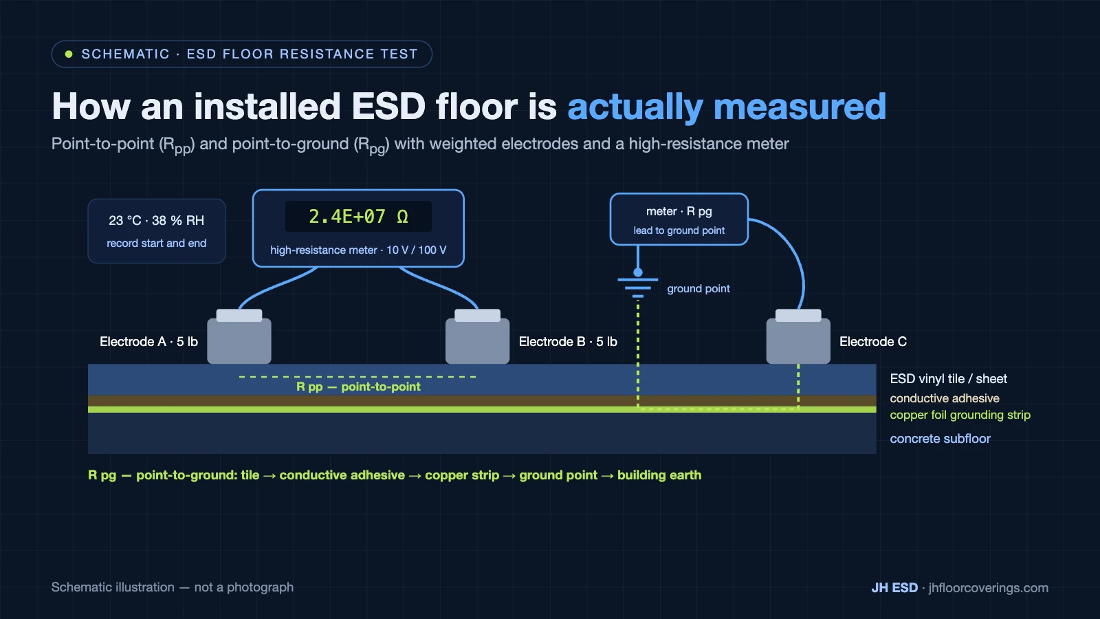
Many teams test ESD flooring the wrong way. They walk onto a freshly installed floor, touch two probes down, read a number, and sign the acceptance form. Then the readings drift, the auditor asks questions, and the project stalls. Proper testing is a system check, not a single measurement.
To test ESD flooring correctly, you need a purpose-built ESD resistance meter with standard weighted electrodes, a defined test voltage, a documented grid of test points, controlled temperature and humidity, a clean and stabilized floor surface, and verified grounding continuity. Acceptance criteria must come from the project's applicable standard, not from a generic number.1
That short answer hides a lot of practical detail. Test voltage, electrode weight, humidity, adhesive coverage, and copper strip continuity all move the number on your display. Below I break down the methods, the equipment, the acceptance logic, and the field variables that cause most disputes.
Why is a multimeter not enough to test ESD flooring?
I get this question almost every month. A contractor buys a handheld multimeter, measures the floor, sees a strange number, and calls me in a panic. The instrument is not wrong. It is simply the wrong tool for this job.
A standard multimeter cannot test ESD flooring because it applies a low test voltage, uses point-contact probes, and rarely reaches the megohm-to-gigohm measurement range required. ESD flooring resistance testing requires a high-resistance meter (megohmmeter) with standardized weighted electrodes and a defined test voltage, typically 10 V or 100 V depending on the standard.
The three technical reasons
1. Range. Most general-purpose multimeters top out in the tens of megohms. Static-dissipative flooring often measures in the 10⁶ to 10⁹ ohm region. Your multimeter will simply show an over-range symbol, and people misread that as "insulating" or "failed."
2. Contact area and pressure. ESD flooring test methods specify weighted electrodes2 — commonly 5 lb (about 2.27 kg) electrodes with a defined conductive rubber contact face. The electrode creates a repeatable contact footprint. Two sharp probes create a tiny, inconsistent contact patch. In customer inquiries and post-installation discussions, we often see two people measure the same tile and report readings an order of magnitude apart, purely because of contact pressure.
3. Test voltage and time. Resistance in polymer-based flooring is voltage-dependent and time-dependent.3 Standards define both the applied voltage and the electrification period so results are comparable. A multimeter applies whatever small voltage its internal circuit provides, for an undefined time.
What you should use instead
- A high-resistance meter / megohmmeter covering roughly 10³ to 10¹² ohms
- Two 5 lb weighted electrodes with conductive rubber faces
- A ground lead and clamp for point-to-ground measurements
- A calibrated thermo-hygrometer for temperature and relative humidity
- Isopropyl alcohol or the specified cleaning agent plus lint-free wipes
> A number without a documented method is not a test result. It is an opinion with a decimal point.
Which standards define ESD flooring testing methods?
Buyers often ask me for "the ESD floor standard." There is no single one. There is a family of documents, and each one answers a different question. Mixing them up is the most common cause of acceptance arguments.
ESD flooring testing is governed mainly by IEC 61340-4-1 (flooring resistance), IEC 61340-4-5 (flooring/footwear/person system), IEC 61340-5-1 and ANSI/ESD S20.20 (program requirements), and ASTM F150 (resistance of resilient flooring).4 Each measures something different, so you must confirm which standard your project specifies before testing.
What each document covers
| Standard | Primary focus | What it measures or specifies | Typical use in a project |
|---|---|---|---|
| IEC 61340-4-15 | Flooring resistance test method | Point-to-point and point-to-ground resistance of installed floor coverings, with defined electrodes and test conditions | Material qualification and site acceptance testing |
| IEC 61340-4-5 | System resistance (person + footwear + floor) | Resistance of the complete walking system to ground, and body voltage generation during walking | Verifying the floor works with the actual footwear used on site |
| IEC 61340-5-1 | ESD control program | Requirements for an ESD control program, including grounding, verification, and periodic testing | Defines why and how often you test |
| ANSI/ESD S20.20 | ESD control program (US) | Program requirements, technical requirements table, compliance verification plan | Audits, customer qualification, EPA certification |
| ASTM F150 | Resistance of resilient flooring | Standard test method for resistance of resilient flooring materials, including electrode and conditioning details | Common in North American specifications and datasheets |
How to read this table in practice
IEC 61340-4-1 and ASTM F150 give you the method. IEC 61340-5-1 and ANSI/ESD S20.20 give you the program logic — what limits apply to your process, how you verify, and how often. IEC 61340-4-5 closes a gap the others leave open: the floor alone does not protect anything. The floor plus footwear plus the person is the actual discharge path.6
I always tell project managers to settle this before mobilization. Ask the end customer one question: which standard and which revision governs acceptance? Then the electrode weight, test voltage, conditioning time, and limits follow from that document. Exact methods and thresholds must be verified against the project's applicable standard — I can describe the landscape, but the contract document decides.
You can review how these documents map to product data in our ESD Flooring System overview.
What resistance ranges count as conductive or static-dissipative flooring?
Here is where specifications get sloppy. Someone writes "anti-static floor, 10⁶ ohms" into a tender document with no method, no voltage, and no measurement configuration. Then nobody agrees on what passed.
Conductive flooring is generally in the order of 10⁴ to below 10⁶ ohms, and static-dissipative flooring is generally in the order of 10⁶ to below 10⁹ ohms.7 These are order-of-magnitude classifications only. The applicable limits, measurement configuration, and test voltage must be verified against the project's applicable standard and test method.
Order-of-magnitude reference
| Class | Typical order-of-magnitude range | Common intent | Note |
|---|---|---|---|
| Conductive | ~1 × 10⁴ to < 1 × 10⁶ Ω | Fast charge removal; often specified where rapid dissipation matters | Verify against the project's applicable standard and test method |
| Static-dissipative | ~1 × 10⁶ to < 1 × 10⁹ Ω | Controlled dissipation with added resistance for personnel safety margin | Verify against the project's applicable standard and test method |
| Anti-static / low charging (marketing term) | Varies widely | Often describes charge generation, not resistance | Verify against the project's applicable standard and test method |
| Insulating | ≥ 1 × 10⁹ to 10¹² Ω and above | Not an ESD floor | Verify against the project's applicable standard and test method |
Why the configuration matters more than the number
Three different measurements share the same unit but answer different questions:
- Point-to-point (Rpp): two weighted electrodes on the floor surface, at a defined separation. This tells you about surface and in-plane conductivity.
- Point-to-ground (Rpg or Rg): one electrode on the floor, the other lead clamped to the building ground or the floor's ground connection. This tests the whole path — floor, adhesive, copper strip, ground wire, connection.
- System resistance (person, footwear, floor): measured per IEC 61340-4-5 logic, with a person standing on the floor in the actual work footwear.
A floor can pass point-to-point and fail point-to-ground. That single fact resolves a large share of the disputes I see. The material is fine; the grounding path is not. See our Testing & Verification page for how installed-system checks are organised.
Also note the practical tension. Very low resistance dissipates charge quickly but reduces the resistive safety margin for personnel near energized equipment.8 Many electronics and semiconductor specifications therefore land in the dissipative band. That is an engineering decision for the facility's ESD coordinator and electrical safety authority — not something a flooring supplier should decide alone. I recommend a qualified ESD professional review application-specific limits.
What equipment and preparation do I need before I test ESD flooring?
Most failed acceptance tests I hear about were not caused by the floor. They were caused by testing in the wrong condition — too soon after installation, on a dusty surface, at 22% relative humidity, with an uncalibrated meter.
Before you test ESD flooring, confirm five things: a calibrated high-resistance meter with correct electrodes and test voltage, recorded temperature and humidity, a cleaned and fully cured floor surface, verified grounding connections, and a documented test-point layout. Testing without these controls produces readings you cannot defend during acceptance.
Pre-test checklist
Instrument
- [ ] High-resistance meter with a range covering at least 10³–10¹¹ Ω
- [ ] Valid calibration certificate, within date
- [ ] Battery condition checked; a weak battery skews high-range readings
- [ ] Instrument self-check or known-resistor check performed
Environment and surface
- [ ] Temperature and relative humidity recorded at the start and end of testing; many project specifications test at the low-humidity end because resistance rises as air dries
- [ ] Floor cleaned with the specified agent and fully dry; no wax, polish, dust or adhesive residue on the test points
- [ ] Adhesive fully cured — test only after the installer's stated curing time, not on the day of installation
- [ ] Any ESD floor finish applied and cured as specified, or clearly recorded as not yet applied
Grounding
- [ ] Copper foil grounding strips laid to the drawing and terminated at the designated ground points
- [ ] Ground point connection to building earth verified with a continuity check before floor testing
- [ ] Number and location of ground points recorded on the test plan
Test-point layout
- [ ] Test points marked on a floor plan, spread across the whole area rather than clustered near the door
- [ ] Extra points at seams, welds, doorways, column bases and any repaired area
- [ ] Each point tagged so a failed reading can be found again after remediation
Why do ESD flooring readings drift or fail after installation?
In customer inquiries and post-installation discussions, we often see the same pattern: the floor passed at the factory, the sample passed on the desk, and then the installed floor reads high, low, or all over the place. Almost every time, the cause sits outside the tile.
Unstable readings usually come from the installed system and the test conditions — adhesive coverage, grounding continuity, surface contamination, humidity, curing time, electrode contact or instrument setup — rather than from the flooring material itself. Work through the variables in order before blaming the product.
| Symptom | Likely cause | What to check first |
|---|---|---|
| Point-to-point passes, point-to-ground fails | Broken grounding path: strip not terminated, poor contact between strip and adhesive, ground point not connected to earth | Continuity from strip to ground point; ground point to building earth; adhesive coverage under the strip |
| Readings high everywhere | Low humidity, uncured adhesive, insulating floor finish or wax, wrong test voltage | Humidity log; curing time against the installer's data; surface cleaned and finish type confirmed; instrument voltage setting |
| Readings vary widely between neighbouring points | Uneven adhesive coverage, dirt or residue under one electrode, inconsistent electrode contact | Clean and re-test the same point; compare electrode weight and contact face; look for adhesive skips at seams |
| One area fails, rest passes | Local contamination, a repaired or replaced section not reconnected to the grid, moisture in the subfloor | Map the failing points; check what changed there; subfloor moisture test |
| Reading changes the longer the electrode sits | Normal electrification time behaviour, or a meter with a weak battery | Hold for the time the standard specifies and record at that moment; check battery and instrument self-test |
| Passed at acceptance, fails a year later | Cleaning with the wrong products, wax build-up, wear, humidity control changed | Cleaning log and product used; strip and re-test a small area; re-check humidity control |
The order matters. Grounding and surface condition explain most disputes and cost nothing to check. Replacing flooring is the last conclusion, not the first.
How should test results be recorded for acceptance?
A pass that nobody can reproduce is not a pass. For a project handover, the test record should let a second person repeat the measurement and get a comparable number.
Record the standard and revision used, the instrument model and calibration date, the test voltage, the electrode type, temperature and humidity, the floor condition, the test-point plan with each reading, and the ground points used. Attach it to the acceptance documents and keep it as the baseline for periodic re-testing.
A minimal record has seven lines per project: standard, instrument, voltage, environment, surface condition, ground-point list, and a table of point-by-point results. Everything else is optional. Everything on that list is not.
Periodic re-testing is part of the program standards, not an extra. Many ESD control programs re-test flooring on a fixed schedule and after any cleaning-product change, repair or refurbishment. Set that interval at handover while the people who installed the floor are still on site.
Frequently Asked Questions
Can I test ESD flooring with a normal multimeter? No. A multimeter lacks the measurement range, the defined test voltage and the weighted electrodes that flooring resistance standards require. Its reading cannot be compared with a specification and should not be used for acceptance.
What is the correct test voltage for ESD flooring? It depends on the standard. Flooring resistance methods commonly use 10 V for lower-resistance floors and 100 V for higher-resistance floors, switching at a defined threshold. Use the voltage the project's applicable standard specifies and record it with the result.
How many test points do I need? Standards and specifications define minimum numbers per area; as a practical rule, spread points evenly across the floor and add points at seams, doorways, columns and repairs. The number should be agreed in the test plan before installation, not decided on the day.
Why does the same floor read differently in summer and winter? Humidity. Resistance in polymer flooring rises as air dries. Specifications often require testing at the low-humidity condition for this reason. Always record humidity with the reading so seasonal differences are explained rather than argued about.
Does a passing resistance test prove the ESD floor is working? It proves the floor and its grounding path meet the resistance requirement under the test conditions. Whether people are protected also depends on footwear, the person-footwear-floor system (IEC 61340-4-5), grounding of equipment and the wider ESD control program.
Conclusion
Testing ESD flooring is a system check. The reading you get depends on the instrument, the electrodes, the voltage, the humidity, the surface, the adhesive, the grounding path and where you put the electrodes — and only then on the flooring material. Fix the method before you argue about the number, take the acceptance limits from the project's applicable standard, and keep a record a stranger could repeat. Do that and most "failed" floors turn out to be fine, and the few that are not get found before anyone signs.
If you are specifying or accepting an ESD vinyl floor and want a second opinion on the test plan, contact JH ESD with the standard, the area and the environment, and we will tell you what we would measure and why.
[Author name], [Title], JH ESD — [n] years answering ESD flooring testing and installation questions for industrial projects.
ESD Association, *Example ESD Control Program Document based on ANSI/ESD S20.20-2014* (PDF). https://www.esda.org/assets/20c36565f2/Sample-ESD-Control-Document-based-on-2020-2014-v2.pdf ↩
ASTM F150-06(2018), *Standard Test Method for Electrical Resistance of Conductive and Static Dissipative Resilient Flooring*. https://store.astm.org/f0150-06r18.html ↩
*Changes in Electrical Conductance of Polymer Composites…*, PMC8036904. https://pmc.ncbi.nlm.nih.gov/articles/PMC8036904/ ↩
ESD Association, *ESD Standards* overview. https://www.esda.org/about-esd/esd-standards/ ↩
IEC 61340-4-1:2003+AMD1:2015 CSV, IEC Webstore. https://webstore.iec.ch/en/publication/22337 ↩
IEC 61340-4-5:2018, IEC Webstore. https://webstore.iec.ch/en/publication/31420 ↩
NASA JSC-66552, ESD control baseline (PDF). https://standards.nasa.gov/sites/default/files/standards/JSC/Baseline/0/JSC-66552BASELINE.pdf ↩
OSHA 29 CFR 1910.333, *Selection and use of work practices*. http://www.osha.gov/laws-regs/regulations/standardnumber/1910/1910.333 ↩